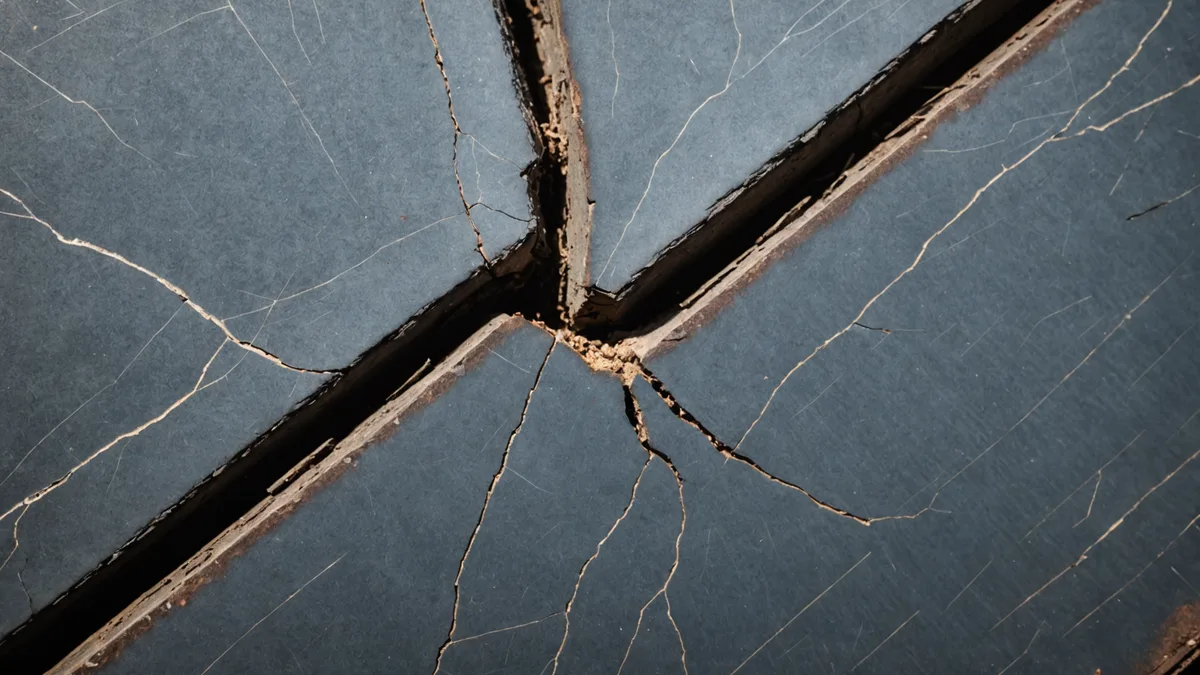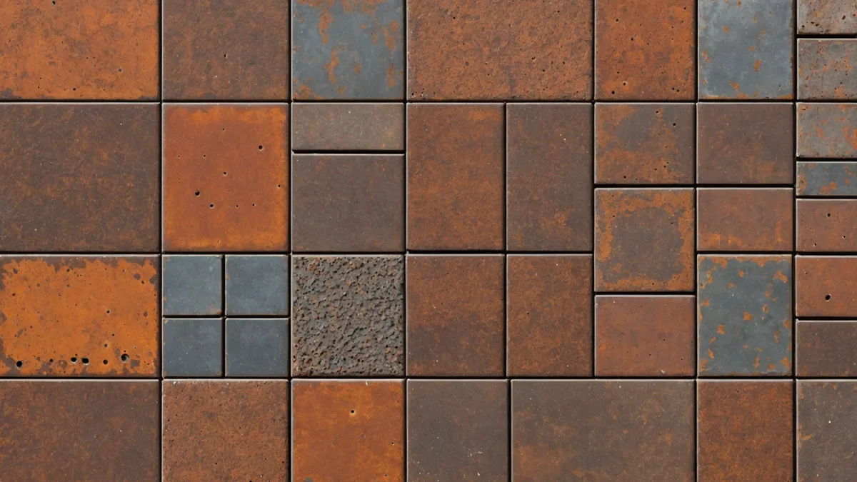
Corrosion detection sounds deceptively simple until you try to train a model to do it. The surface of weathered infrastructure steel is not a clean background with labeled defect objects sitting on top. It is a textured, heterogeneous material with normal oxidation, surface contaminants, coating residue, environmental staining, and actual structural defects all producing visually similar patterns at first glance. The model has to learn to distinguish all of these, and the path from raw imagery to reliable classification is more involved than a standard object detection problem.
This post describes how we approach defect taxonomy and what the model actually learns to look for when we ask it to find early-stage corrosion on transmission steel.
Why Standard Object Detection Falls Short
Most computer vision practitioners are familiar with object detection in the form of bounding-box classification: find the object, draw a box, label it. That paradigm works well when the thing being detected has a consistent shape, defined boundary, and clear separation from background. A car in a parking lot. A face in a photo.
Infrastructure corrosion does not behave that way. Early-stage surface pitting might be 2 to 5mm in diameter, irregular in outline, and distributed across a large surface area at unpredictable density. The distinction between "surface oxidation that is cosmetic" and "surface pitting that represents early structural risk" is not a shape or size distinction. It is a morphological one: the depth profile of the pit, the pattern of mineral deposition around its rim, the presence of secondary cracking at the pit boundary. Those are not features that bounding-box detection captures naturally.
For corrosion detection specifically, the useful approach is closer to semantic segmentation combined with per-region classification. The model segments the surface into regions and assigns each region a category from the defect taxonomy. That lets it handle variable-density defect distributions without requiring each individual pit to be enumerated as a separate detection event.
Building the Defect Taxonomy First
Before writing any training code, we had to settle on the taxonomy. The taxonomy is the backbone of everything downstream: what the model learns to distinguish, what the annotation labels mean, and what the output report categories correspond to.
We built ours around five primary categories, each with distinct visual signatures and distinct maintenance implications:
Surface pitting is the early-stage formation of localized cavities in the steel substrate. Pits in the 0.5 to 5mm range are the primary detection target at this stage; smaller than that and the optics become the limiting factor rather than the model, larger and the condition has already progressed beyond early intervention.
Oxidation banding is the pattern of galvanic corrosion that develops at dissimilar metal contact zones, particularly at bolt interfaces and where galvanized steel meets a different metal grade. It presents as a characteristic streaked or banded discoloration with a distinct mineral deposit texture that differs from general surface oxidation.
Coating delamination is the separation of protective coating from the substrate surface. It precedes visible corrosion by weeks to months depending on environmental conditions, making it the highest-value early warning category. Delamination produces characteristic micro-blistering patterns that are visually distinct from intact coating at the right imaging resolution.
Crack initiation at surface level, typically at stress concentrations and weld heat-affected zones. These are fine-line features that the model distinguishes from surface scratches by the directionality and edge sharpness of the feature relative to the surrounding surface texture.
Mechanical wear at bolt seats and joint interfaces: the deformation and material loss patterns associated with load cycling and fretting corrosion in mechanically loaded joints.
The taxonomy is deliberately kept to five categories at the top level. Finer subcategories exist in the annotation schema, but the model outputs five primary classes plus a confidence score. Maintenance engineers need actionable categories, not a 20-class taxonomy that requires interpretation.
What Makes Annotation Hard in This Domain
Annotation quality is the limiting factor in infrastructure defect detection, more than model architecture. We have spent more time developing annotation guidelines and reviewing annotator consistency than on any other part of the perception pipeline.
The core difficulty is that the distinction between defect categories is sometimes genuinely ambiguous in a single image. A region of surface oxidation and an early-stage pit can look nearly identical in a single frame at moderate resolution. The annotation decision often requires contextual judgment: is this a dark spot because of a shadow, surface contamination, or an actual pit? In uncertain cases, annotators are instructed to mark the region with an uncertainty flag rather than force a label. Those flagged regions are excluded from loss computation during training and used in a separate evaluation pass.
We also deal with the class imbalance problem inherent to early-stage detection. A transmission steel surface in reasonable condition might have 95% of its pixels in the "background/normal" category and 5% or less across all defect categories. Training naively on that distribution produces a model that learns to predict "normal" for everything and achieves high pixel-level accuracy while being useless for the actual task. Standard approaches like focal loss and oversampling of defect-positive patches are part of the training recipe, but getting the balance right requires iteration against held-out evaluation sets with representative defect densities.
What the Model Actually Learns to Look For
After enough training iterations, the learned features start to reveal what distinguishes the categories in practice. This is where the computer vision problem gets interesting from an engineering standpoint.
For surface pitting, the model's attention concentrates on local texture discontinuities: regions where the surface normal changes abruptly relative to the surrounding surface, producing a characteristic shadow pattern at shallow lighting angles. This is consistent with how a human inspector with a raking light flashlight approaches the same detection task. The model learned a version of what experienced inspectors describe as "looking for the shadow."
For coating delamination, the discriminating feature appears to be the high-frequency edge density within a region combined with a specific spectral signature. Delaminating coatings produce fine blistering edges at a scale that intact coating does not, and there is a characteristic color shift in the delaminated zone before visible rust appears. The model learned to combine those two signals.
For oxidation banding at dissimilar metal interfaces, the spatial relationship matters as much as the local texture. The model learned to use proximity to bolt holes and joint edges as context for interpreting ambiguous surface color patterns. A dark stain near a bolt interface has a different prior than the same stain in the middle of a flat panel section.
Resolution and Speed Tradeoffs on a Moving Platform
An important practical constraint is that the robot is moving during capture. This is different from laboratory inspection or stationary imaging, and it creates a fundamental tradeoff between coverage speed and image resolution.
At crawl speeds of 50 to 80mm per second on a lattice member, capturing images at 2fps with a fixed focal length gives you a certain ground sample distance per pixel. For early-stage pitting detection at the 1 to 3mm scale, you need ground resolution better than roughly 0.5mm per pixel at typical working distances of 200 to 400mm. That constrains the lens specification and the imaging geometry quite tightly.
We are not claiming that current hardware fully closes this tradeoff for all defect categories at all crawl speeds. For delamination detection the requirements are less strict; the features are larger-scale. For sub-millimeter crack initiation, the requirements are at the edge of what mobile platform imagery can reliably deliver. This is an honest statement of where the system sits on the capability curve, not a claim that the problem is solved.
Where the Difficulty Is, Honestly
The hardest ongoing problem is false positive rate on the pitting category under certain lighting conditions. When the robot traverses a section with varying ambient light (partial shadow from adjacent structure, direct sun angles at low elevation), the shadow-based texture cue that the model uses for pitting detection produces false positives on legitimate surface features like weld marks and surface preparation textures. The current mitigation is a confidence threshold calibrated against that specific condition class, but it is not a complete solution.
The detection approach we have described is fundamentally visual. It works well for surface and near-surface defects where the morphological signature is detectable with optical imaging. For subsurface corrosion and wall-thickness reduction in pipeline applications, visual detection alone is insufficient, which is why the full sensor payload includes thermal and ultrasonic modalities. But that is a topic for a different post.