When we talk about the defect detection problem in infrastructure inspection, surface corrosion and weld-seam fatigue cracks get grouped together as if they were the same type of problem. They are not. The detection requirements, the morphological signatures, the failure mode trajectories, and the appropriate sensor response are different enough that conflating them leads to significant gaps in inspection coverage.
This post focuses specifically on weld-seam fatigue cracks: what makes them visually distinct from surface corrosion, why propagation patterns matter for severity assessment, and how the detection problem differs technically from the surface pitting detection we described in an earlier post.
The Failure Mode Difference
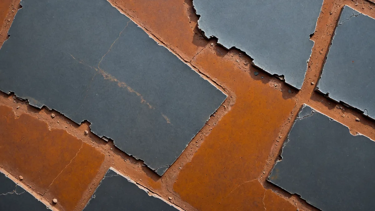
Surface corrosion is a thermodynamic process. It proceeds continuously in the presence of the right conditions, oxygen, moisture, electrochemical potential difference, and the rate depends on those conditions rather than on the load history of the structure. Early-stage surface corrosion is not necessarily structurally significant on its own; it becomes a concern when it reduces wall thickness, compromises protective coating, or creates stress concentrations that combine with load cycling.
Weld-seam fatigue cracking is a mechanical failure mode driven by cyclic loading. The structural steel in a transmission tower is subject to wind-induced vibration at the tower's natural frequencies, thermal cycling from daily and seasonal temperature swings, and ground motion transmission from vehicles and other sources. These load cycles produce small plastic strain increments at stress concentrations, and over time those increments accumulate into microstructural damage that nucleates into a visible crack.
The fundamental difference is trajectory: surface corrosion, if caught early, can be addressed by surface treatment and coating restoration without affecting structural integrity. A fatigue crack that has propagated to visible length has already progressed through the nucleation and early propagation phases. Depending on its location and the stress intensity factor at its tip, it may be close to the critical crack length beyond which propagation accelerates rapidly toward fracture. Early detection has a much smaller intervention window for fatigue cracks than for surface corrosion.
Where Fatigue Cracks Form on Transmission Tower Steel
Fatigue cracks in lattice tower steel preferentially initiate at two types of locations: welded connections and regions of geometric stress concentration.
Welded connections are the primary concern because the welding process introduces residual tensile stresses in the heat-affected zone (HAZ), the region adjacent to the weld bead where base metal was heated above its recrystallization temperature but not fully melted. The HAZ microstructure is coarser-grained and more brittle than the base material, and residual tensile stresses in this zone mean the material is effectively pre-loaded before any service load is applied. Fatigue crack initiation is dramatically accelerated in residual tensile stress fields, which is why weld toes are the highest-priority inspection targets for fatigue.
Geometric stress concentrations occur at abrupt changes in cross-section, at bolt holes, at gusset plate terminations, and at any location where the load path through the structure changes direction sharply. At these locations, the stress in the material is locally higher than the nominal stress by a factor called the stress concentration factor (Kt), which for typical structural details ranges from 1.5 to 5 or more. Higher local stress means fatigue crack initiation occurs at fewer load cycles.
For an inspection robot, this means the highest-value inspection effort is concentrated on weld toes, gusset plate terminations, bolt hole edges, and cross-member connection points, rather than uniformly distributed across all surface area.
Visual Morphology of Fatigue Cracks vs. Surface Marks
The training challenge for a crack detection model is that fatigue cracks share visual features with several non-defect surface conditions. Scratches from installation and maintenance activity. Machining marks from original fabrication. Scribe lines from layout and fitting operations. Coke deposits and surface staining that produce linear dark marks on lightly corroded steel. All of these can look crack-like at a glance and produce false positives in a model that is not trained to distinguish them.
The distinguishing morphological features of a propagated fatigue crack are:
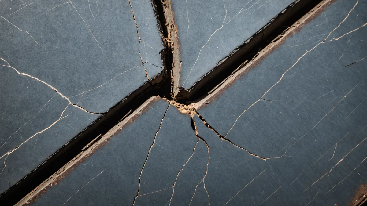
Edge sharpness and continuity: Fatigue cracks have sharp, clean edges with high local contrast against the background surface. Their edges are continuous, not segmented or interrupted. Scratches often have a more diffuse edge profile where the deformed material at the scratch edge scatters light differently than a true crack opening.
Directionality consistent with the local stress field: Fatigue cracks propagate perpendicular to the maximum principal tensile stress. At a weld toe, this means they propagate away from the weld into the base material, typically at 90 degrees to the weld seam direction. Incidental surface marks do not respect this geometric relationship.
Width profile: A propagated fatigue crack is widest at its mouth (the point of highest opening displacement) and tapers toward its tip. The width taper follows a characteristic profile related to the stress intensity factor distribution along the crack front. Scratches and machining marks have more uniform width profiles.
Absence of deformation ridge: A scratch or gouge typically has a ridge of displaced material along its edges where material was plastically deformed rather than separated. A fatigue crack does not; the material separated along a grain boundary or cleavage plane without the lateral deformation that produces ridges. At high enough resolution, the edge profile distinguishes these two cases.
Detection Approach for Crack Signatures
The detection approach for cracks differs from the approach for surface pitting in important ways. Pitting is a distributed area phenomenon; the model segments regions by defect category density. Cracks are linear features; the detection task is closer to thin-structure segmentation, which has its own set of architecture considerations.
Thin-structure segmentation problems, fine-grained cracks, vessel boundaries in medical imaging, road lane markings, require either very high spatial resolution in the feature maps or explicit architecture components for capturing linear structure. Standard convolutional encoder-decoder architectures tend to under-segment thin, high-aspect-ratio features because pooling operations lose the fine spatial information needed to reconstruct narrow structures at output resolution.
Approaches we have found useful include attention-gated upsampling paths that weight spatial detail recovery based on the crack probability at each spatial location, and multi-scale feature fusion that explicitly combines high-resolution low-level features with low-resolution high-level semantic features for the final segmentation output. These are not novel architectural ideas; they appear in the thin-structure segmentation literature. Applying them to fatigue crack detection in infrastructure steel is the domain-specific adaptation.
The Propagation Pattern Classification Problem
Detecting that a crack is present is the first step; assessing how far it has propagated and how fast it is likely to continue is the maintenance-relevant question. Propagation pattern classification adds another layer to the detection task.
Key propagation indicators visible in surface imagery include crack length, the orientation change along the crack path (a crack that turns abruptly may have encountered a grain boundary or microstructural feature), the presence of branching at the crack tip (a sign of high stress intensity), and secondary cracking in the HAZ parallel to the primary crack. These features require both spatial resolution and semantic understanding of crack morphology, which is why they are best handled as separate classification steps applied to detected crack instances rather than as part of the primary detection pass.
We should be direct about a fundamental limitation here: visual surface inspection of a crack cannot determine crack depth. A surface crack 10mm long could be 0.5mm deep or 5mm deep depending on the loading history and material properties, and the maintenance implications are very different. Determining crack depth requires a complementary non-destructive method, typically phased-array ultrasonic testing (PAUT) or alternating current field measurement (ACFM), applied specifically to the locations that visual inspection flagged. Visual detection identifies the cases that warrant further investigation; it does not provide the complete characterization needed for a fracture mechanics disposition.
Why This Matters for Inspection Prioritization
A practical consequence of the difference between surface corrosion and fatigue crack detection is that they should drive different inspection scheduling logic. Surface corrosion findings can generally tolerate a monitored waiting period before action; the condition is slow-moving and additional data points from future inspection cycles help confirm the progression rate. Fatigue crack findings at structurally significant locations warrant faster follow-up with the complementary methods described above, because the propagation-to-fracture transition can be non-linear once the crack reaches a critical length.
The inspection report needs to communicate this difference clearly to maintenance engineers. A flat severity scale that treats all defects the same misses the distinction. Our defect taxonomy and report format are designed to call out fatigue crack findings explicitly, with different follow-up guidance than the corrosion categories, precisely because the maintenance response should be different.