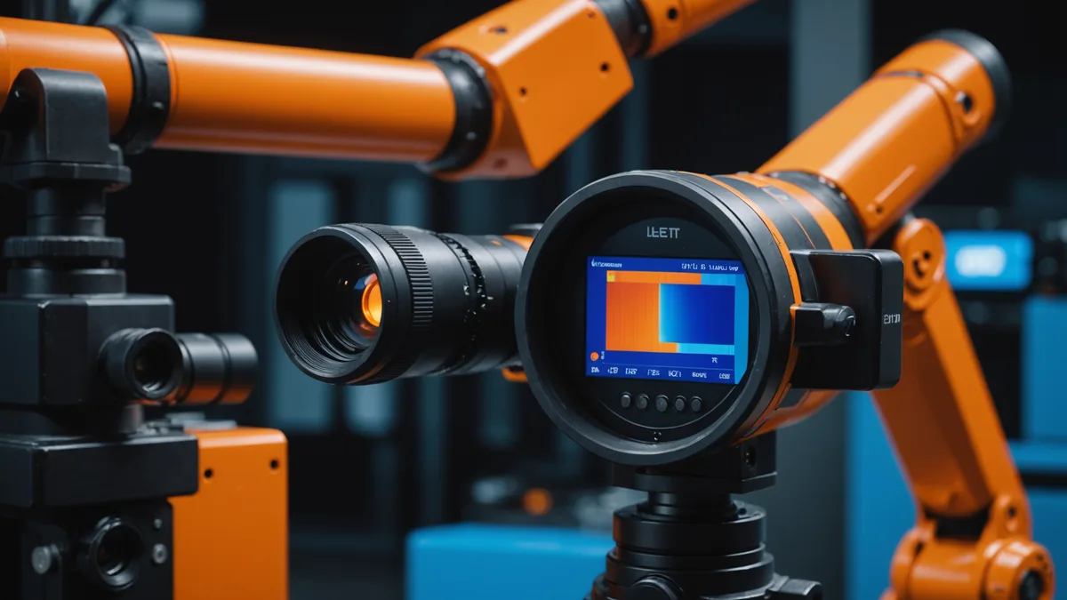
Designing a robot that climbs transmission tower lattice is a constrained mechanical problem in ways that standard mobile robot design does not prepare you for. The geometry is irregular, the environment is actively hostile, and the load cases include wind at height. This post covers the main mechanical tradeoffs we worked through in the chassis design.
The Lattice Is Not a Uniform Surface
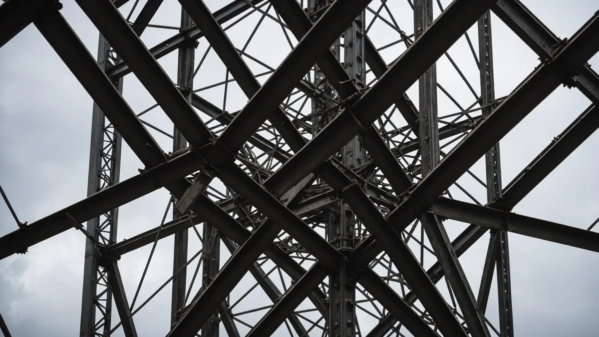
Transmission tower lattice is built from multiple member types within a single structure. The main legs are typically large angle-iron sections or tubular steel columns. Cross-bracing members are smaller-diameter tubes or flat bar stock. Diagonal tension rods are smaller still. Within a single tower, member cross-sections change by zone: larger at the base where structural loads are highest, smaller toward the apex where they are lighter but still need to carry wind and conductor sway loads.
Added to this, older towers carry decades of maintenance history. Splice plates bolted over repaired sections create step changes in surface profile. Weld repairs add local protrusions. Re-galvanizing cycles build up coating thickness unevenly. A robot that relies on flush contact with a predictable surface profile will struggle with all of this.
We surveyed a range of US lattice tower types before settling on the first chassis geometry. The variation is substantial. Towers designed to different era standards, different regional codes, and different load requirements have meaningfully different member proportions. Consider a typical 345 kV double-circuit tower from the 1970s versus a modern 500 kV single-circuit lattice structure: leg section diameter, bracing angle geometry, and cross-member profile differ enough that a grip system calibrated for one will encounter surprises on the other.
Our working assumption is that any real deployment will involve tower types outside the specific range we tested against. The chassis has to handle that gracefully, which means the grip system must accommodate a meaningful range of member cross-sections and surface profiles rather than a single nominal geometry.
Wind Loading at Height Is a Continuous Design Condition
On a ground platform, wind loading is not a serious design consideration in most cases. On a robot climbing at 40 to 60 meters elevation on an exposed tower structure, it becomes a constant force input that the grip system has to resist and that the chassis structure has to carry without deflecting enough to affect sensor pointing geometry.
The force magnitudes are not extreme. A 40 km/h lateral wind on a chassis with roughly 0.04 square meters of frontal area produces somewhere in the range of 10 to 15 N of lateral force. That is manageable. The problem is the combination of lateral force with the already-loaded grip contact on a curved or angled member surface.
We observed a specific failure mode in early prototype iterations where the chassis would walk slowly around the member axis under sustained lateral load. The grip provided enough normal force to support weight, but not enough rotational resistance to prevent the angular creep. The fix involved adding a secondary engagement feature that indexed the chassis against the member web rather than relying on the contact pad geometry alone. It added about 200 grams to the chassis mass, which then created pressure elsewhere in the mass budget.
Wind also affects imaging quality. The chassis is not perfectly rigid, and at height the member it is gripping also moves under wind load. We switched from fixed-interval frame capture to event-triggered capture with a short stability check based on IMU data. The penalty is run time: roughly 15 to 20 percent longer inspection runs. The benefit is materially better image sharpness and consistent geometric fidelity across frames, which matters for the defect classification step downstream.
Grip Mechanism: Magnetic Attraction Versus Mechanical Clamping
Transmission tower steel is ferromagnetic, which makes permanent-magnet grippers an attractive design choice. They are passive, have no moving parts in the contact element, conform to some degree of surface variation, and require no actuation energy to maintain grip. Within a specific operating range, there is nothing to criticize about them.
The range has hard limits. As the angle between the member face and the magnet pad increases, contact area drops and effective grip force drops faster than linearly because the fringe field geometry changes. On diagonal bracing members that carry the highest dynamic load during lateral wind events, purely magnetic grip does not provide sufficient margin on the steeper angles we encounter.
Galvanizing thickness variation across different towers also affects grip force. The standoff distance between the magnet surface and the underlying steel substrate is set by the zinc coating thickness. Even a few extra millimeters of accumulated zinc from multiple re-coating cycles makes a measurable difference in magnetic attraction force. This is not a failure mode you can calibrate away at design time because you do not know which specific towers the robot will be deployed on.
Mechanical clamping provides grip force that is largely independent of surface coating thickness, but it introduces actuator complexity, requires position sensing to close the clamp correctly, and adds failure modes if the clamp sensor is miscalibrated or drifts.
The current design uses magnetic attraction as the primary mode on flat member faces, with a mechanical engagement feature added for the diagonal bracing zones. Two grip modes, not one. More mass and more control complexity than we initially wanted. But it handles the geometry and coating-thickness range we encounter more reliably than either approach alone, and reliability in the middle of a 50-meter climb is a hard requirement, not a preference.
The Mass Budget Problem
Every kilogram added to the climbing chassis must be supported by the grip system throughout the entire climb. The grip force margin, the motor torque envelope, and the overall chassis mass are tightly linked. Designing the chassis to be stiffer adds mass, which requires more grip force, which either increases actuator size (adding more mass) or reduces the safety margin. There is no free lunch.
We worked from a target chassis mass under 8 kg for the structural frame, not counting sensor payload. That target came from the grip force envelope at maximum bracing angle, the motor duty cycle limits at the motor sizes that fit the chassis geometry, and a safety factor on the worst-case combined load we planned to design against. It is not a conservative number. There is not a lot of margin built in.
Achieving that mass with adequate torsional stiffness required using 7075 aluminum alloy for the main structural frame and carbon-fiber composite for the longitudinal spine sections that carry most of the bending load. A pure aluminum design would have been simpler to machine and easier to repair in the field but would have been roughly 1.8 kg heavier at equivalent stiffness. The composite spine adds fabrication complexity and makes field repair harder, which is a real tradeoff, not just a number on a spreadsheet.
The sensor payload adds 1.5 to 2.5 kg depending on configuration. The base chassis budget has to carry margin below the 8 kg target to accommodate this range. When we first assembled a fully-loaded chassis with the heavier sensor configuration, we were 340 grams over the target. That required a second-pass mass reduction on three structural brackets before the system came in correctly.
Material Selection in a Galvanic Environment
Galvanized steel and aluminum in direct contact on a wet surface is a galvanic corrosion pair. Rainwater provides the electrolyte. Extended contact time during inspections means the pair has time to react. Left unaddressed, this degrades aluminum contact surfaces over repeated runs and eventually affects grip geometry.
The isolation approach is established: non-conductive backing on all grip contact surfaces, anodized aluminum for external structural members, and stainless steel for all external fasteners. These are standard practices borrowed directly from aerospace and marine hardware design.
The less obvious issue is the electronics enclosure. Moisture ingress is the obvious failure mode, but galvanic-driven corrosion on connector seams and housing interfaces happens slowly enough to escape notice until a connector fails mid-operation. All external connector bodies use stainless steel housings. All housing seams are sealed to IP67 rating minimum. We treat enclosure seal integrity as a maintenance-cycle inspection item because seal degradation is a time-and-cycle dependent failure mode rather than a once-and-done design decision.
What We Still Do Not Know
To be direct about the current state: the chassis handles the geometry range and wind conditions we have tested against. That is a narrower statement than it sounds. Testing has been controlled and deliberate. The conditions a robot encounters on aged infrastructure across different regional environments will include combinations we have not planned for.
We are not suggesting that controlled testing is insufficient to build a design on. We are saying that the data we need to understand long-term durability comes from actual operational run-time, and we do not yet have that. Grip actuator cycle count to first failure under field loading, seal degradation rate under cycling temperature and humidity, magnetic array behavior after extended exposure to transmission line induction fields: these require logged operational data to characterize properly.
The current design is good enough to start gathering that data, and the architecture is designed to allow component updates as it comes in. That is probably the most honest summary of where things stand on the chassis side.