Corrosion Under Insulation, often abbreviated CUI, is one of the most expensive failure modes in the petroleum, petrochemical, and industrial process pipeline sectors. It is also among the hardest to detect with conventional inspection methods. This post explains why CUI is structurally invisible to standard inspection approaches and what thermal sensor payloads change about that detection problem.
Why Insulation Creates the Problem
Pipeline insulation exists to manage heat: maintaining process temperature in heated lines, preventing freezing in cryogenic applications, and reducing energy loss in steam systems. The insulation typically consists of a fibrous or cellular core material wrapped around the pipe and covered by an outer metal jacket, usually galvanized steel or aluminum sheeting, to protect against mechanical damage and weather ingress.
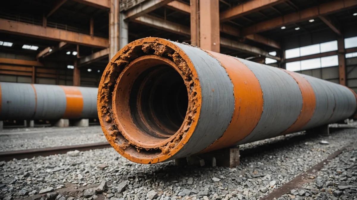
The insulation jacket is not fully sealed. Water enters through jacket seams, end terminations, penetrations for support brackets, and any damage to the outer cladding. Thermal cycling causes the jacket to flex and gap at joints. Insulation materials that were installed dry gradually accumulate moisture over years of service. Once water is present between the insulation layer and the pipe surface, it stays there. Drainage geometry is typically poor. The environment inside the insulation annulus, warm, humid, and in contact with both the pipe metal surface and mineral or synthetic insulation material, is nearly optimal for corrosion initiation.
The pipe wall loses material from the outside while the process fluid inside provides no visible indicator. The pipe looks insulated and intact from the outside. The insulation looks undamaged from the outside. The corrosion progresses underneath without any detectable surface signal.
The Temperature Window Where CUI Happens Most
CUI is not uniformly distributed across all pipeline service temperature ranges. It concentrates in two main windows. The first is the cyclic wet range from about 0 degrees Celsius to 60 degrees Celsius. At these temperatures, liquid water can persist in the insulation annulus across many operating cycles. The pipe surface does not get hot enough to dry out the insulation zone between cycles, so moisture accumulates over time.
The second window is above 60 degrees Celsius for lines with steam or process heat excursions. Here the driving mechanism is condensation cycling rather than permanent moisture accumulation. When a heated line goes through shutdown and restart, the pipe surface cools, condensation forms on the inner jacket surface, water wets the insulation, and the next heat cycle drives some of it toward the pipe wall before drying the rest out. The net effect is repeated wet-dry cycling at the pipe surface, which is more aggressive than continuous wetting for many corrosion morphologies.
Pipelines operating continuously above approximately 120 degrees Celsius are generally not CUI candidates because the insulation annulus stays too hot for liquid water to persist. This is widely documented in NACE SP0198, the industry standard covering CUI mitigation. The practical upshot is that a large fraction of industrial process piping, particularly in the refinery and petrochemical sector, sits in one of the two risk windows.
What Manual Inspection Misses and Why
The standard CUI inspection workflow involves selecting sections of insulated piping believed to be at higher risk (based on age, service history, pipe geometry, and past maintenance records), stripping the outer jacket and insulation from those sections, visually inspecting the pipe surface, and then re-insulating. It is expensive, time-consuming, and disruptive to operations on active systems.
More importantly, it is sampling. Deciding which sections to strip and inspect requires a risk prioritization judgment made before the inspection. That judgment is based on what is known about the line history, which is often incomplete for older infrastructure. Sections that look low-risk based on available records get deprioritized, and those are exactly the sections where surprise failures occur.
The sampling approach also does not scale well with inspection frequency requirements. NACE SP0198 and industry CUI programs recommend inspection intervals that vary by service history and risk category, but even the lower-frequency categories require periodic wall loss measurement across large insulated surface areas. A refinery with hundreds of meters of insulated piping cannot practically strip and re-insulate everything on the required cycle. Coverage is necessarily incomplete.
Some operators use radiographic techniques, particularly pulsed eddy current (PEC) or real-time radiography, which can measure wall thickness through insulation without stripping. These are effective where they are applied but require specialized technicians, significant equipment, and access positioning that is difficult on elevated or confined piping runs.
How Thermal Imaging Changes the Detection Window
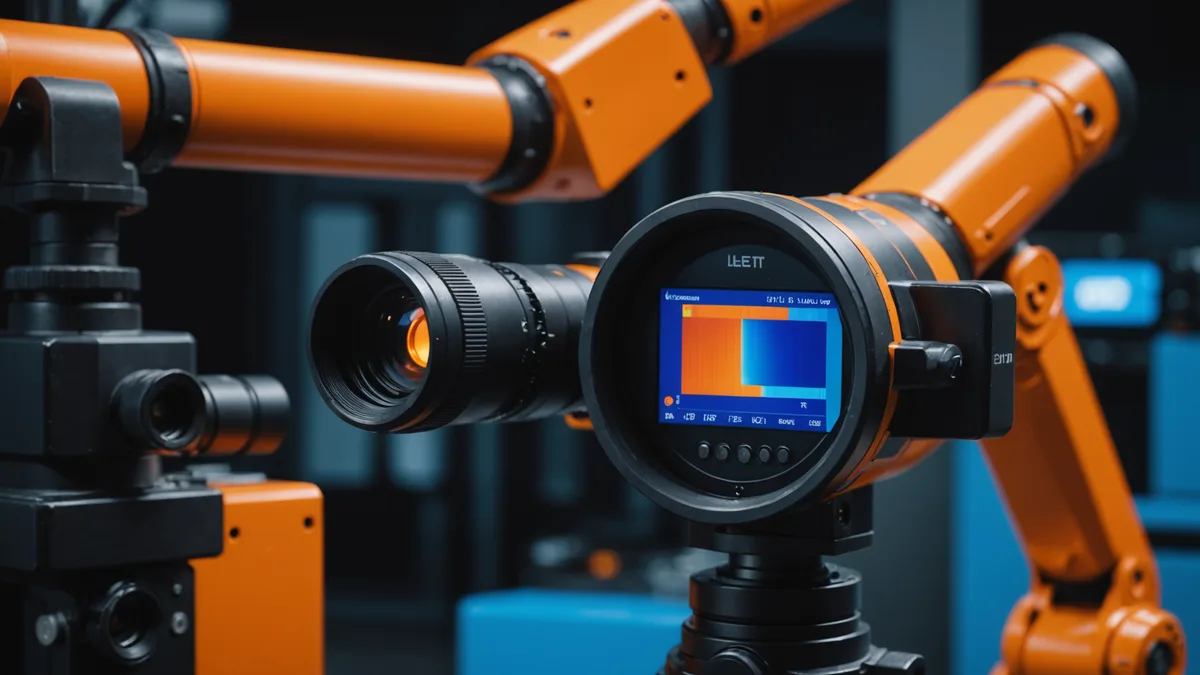
CUI alters the thermal signature of an insulated pipeline surface. Corroded metal and wet insulation both have different thermal conductivity than intact steel covered by dry insulation. The temperature distribution on the outer jacket surface is therefore not uniform when CUI is present. A thermal camera scanning the outer jacket surface observes anomalies in that distribution that correspond to subsurface conditions.
The physics here is straightforward. A section where insulation has absorbed moisture and the pipe wall has thinned conducts heat differently than a section where both are intact. The outer jacket temperature in the anomalous zone deviates from the expected smooth gradient. The deviation magnitude depends on the thermal differential of the process fluid, the ambient temperature, and the severity of the condition, but it is measurable with current thermal imaging hardware at sufficient spatial resolution.
The detection limit is not zero degradation. Early-stage CUI with minimal moisture uptake and surface pitting produces smaller thermal signature deviations than advanced-stage corrosion with significant wall loss and saturated insulation. This is an important qualification to be clear about: thermal imaging identifies anomalies that warrant further investigation, not confirmed severity levels. It shifts the inspection workflow from blind sampling to targeted stripping based on actual thermal evidence.
The practical benefit of this shift is significant even with an imperfect detection limit. If thermal scanning can identify the 20 percent of insulated pipeline surface area where 80 percent of CUI activity is concentrated, the strip-and-inspect effort is dramatically more efficient than random or risk-model-based sampling. That does not require detecting every early-stage lesion; it requires that advanced-stage and moisture-active CUI zones show up reliably. The evidence from existing utility thermal inspection programs suggests that threshold is achievable in the operating conditions where CUI risk is highest.
What a Robot Platform Adds to This
Handheld thermal inspection of insulated piping is already practiced by some operators. The constraint is coverage and consistency. A technician with a handheld thermal imager covers some sections of accessible surface at irregular angles and speeds. The result is incomplete and difficult to compare systematically between inspection cycles because there is no consistent positional reference.
A crawling robot on the pipe exterior can maintain consistent stand-off distance from the outer jacket surface, cover a full pipe circumference at each longitudinal position, and record a thermal map with position metadata from an onboard IMU and odometry system. That positional metadata is what turns a thermal image into actionable inspection data: instead of "this section looks warmer than expected," the output is "this pipe segment at 14 meters from the junction marker has a thermal anomaly at the 7 o'clock position on the outer jacket."
There is also a consistency benefit for change detection. A first inspection run establishes a baseline thermal map for the pipe section. Subsequent runs can be differenced against that baseline rather than evaluated purely on absolute temperature thresholds. Change detection with a positional reference is considerably more sensitive than threshold-based absolute detection, particularly for slow-progressing conditions that are below the absolute detection threshold on any single run but measurably changing across inspection cycles.
The Cases Where Thermal Does Not Help
To be specific about the limitation: thermal imaging is not a good CUI detection method for lines operating near ambient temperature with minimal thermal gradient across the insulation. At low temperature differential between process fluid and ambient, the outer jacket surface does not carry enough thermal contrast to distinguish CUI-affected zones from intact zones. For truly ambient-temperature insulated lines, wall-measurement techniques such as PEC remain necessary.
It is also not a replacement for wall-thickness measurement once a CUI zone is identified. Thermal imaging identifies locations that warrant further investigation; it does not quantify the wall loss or make a run-or-repair decision. That step still requires either strip-and-measure inspection or an ultrasonic wall measurement technique at the flagged location. The value is in focusing that effort, not in eliminating it.
These are real constraints, not edge cases. A complete CUI management program for a mixed-service pipeline network would use thermal scanning for coverage on thermally active lines and reserve direct measurement techniques for the subset of lines where thermal does not generate useful contrast. The approach is complementary, not a wholesale replacement of existing methods.